
Tuesday, June 30, 2015
Giving old tech a new life
But lately my home office has become so cluttered that even Oscar Madison would be appalled at the mess. So I spent a day going through all the old parts I’ve kept around to fix broken computers and weeded out anything more than a few years old.
Those really old parts were a significant portion of my stash, and as I looked at them stacked on my office floor, I couldn’t quite bring myself to just put it all in the trash.
So I decided to give some of those parts new life out in my workshop. The following pictures detail the process I used to turn an old IDE controller card and a broken hard drive into a desk clock.
| 1. I started with a platter from an dead hard drive, an IDE controller card and clock motor. Then gathered some tools: a hot glue gun, a pair of needle-nose pliers and a few other things, like calipers, a hacksaw and drill which aren't pictured here. | 
|
| 2. Using the needle-nose pliers, I removed some of the capacitors on the IDE card. They were in the way of where the clock face was going to go. I didn't feel like going through the trouble of desoldering them, so I just pulled them off, brute-force style. |
 |
| 3. Next I positioned the platter from the old hard drive on the IDE card and marked the center where the spindle for the clock motor needed to come through. |  |
| 4. I took a pair of calipers and measured the thickness of the clock spindle. It was 3/8". |  |
| 5. So I loaded a 3/8" drill bit into my drill press... |  |
| 6. ... and positioned the bit over the mark I made on the card ... |  |
| 7. ... and drilled a hole in it. The drill bit I used was old and not that sharp -- because I didn't want to ruin one I use for my "real" woodworking projects -- but it cut through that card with surprising ease. |  |
| 8. I checked the fit of the clock spindle and once I saw it fit perfectly, I hot glued it to the back of the card. |  |
| 9. Next I took an O ring that came from the dead hard drive and placed it on the card. I needed this to hold the platter of the hard drive off the card, so the "clock face" would clear that big chip you see pictured at right. Since that O-ring overlapped that chip too, I marked the portion I needed to trim away... |  |
| 10. ... and using a mini-hack saw, I cut it away. |  |
| 11. Once cut to fit, I hot glued that to the face of the IDE card. |
|
| 12. I then clamped the card to my work bench so I could remove the little hook on the bracket that secured the card to the computer case. The metal wasn't that thick, but it still took significant effort to cut through it. There's got to be a better way to do this safely with a power tool! |  |
| 13. All that work just to get rid of that little hook! |  |
| 14. And because I'm a perfectionist, I just had to square up the other end of that bracket. That took another few minutes.... |  |
| 15. After that it was back to the drill press to punch holes in that metal bracket so I could screw it to a wood base. I used a newer bit here with a squirt or two of WD40 for lubrication and the bit punched right though the thin metal fine. |  |
| 16. Back at my workbench, I hot glued the platter onto the O ring then used the ring that secured the platter to the spindle of the hard drive's motor to cover the center part of my new clock's face. This too was hot glued down. | 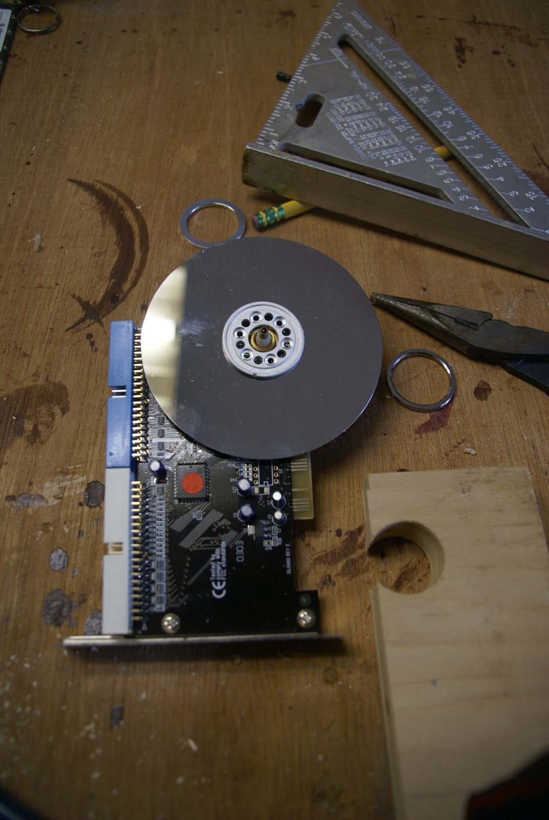 |
| 17. I next attached the clock hands and one of the old IDE ribbon cables to a connector on the side of the clock. | 
|
| 18. One of the things about being a woodworker is that I hardly ever throw away a scrap piece of wood, because, like most woodworkers, we never know when it might come in handy. Well this old test drawer front I made for a project several years ago was just about the perfect size for the clock base. Just needed to be trimmed down a bit on my chop saw. (I could have certainly used a handsaw for this, but my chop saw was right next to my bench and far faster...) After cutting it, I did have to use my router add the fancy profile to the side I cut. For some reason I forgot to photograph that setup, so you're just going to have to take my word for it! |  |
| 19. With the base on my bench I marked out where I wanted the bracket to go on it. |  |
| 20. Then I placed the clock on the base and figured out where I wanted the ribbon cable to attach. I finally decided on the position you see here. |  |
| 21. To prove to myself I could cut a mortise by hand, I drilled out this slot and cleaned it up with some chisels. It wasn't as hard as I thought it would be, so I think I might do mortises this way in my next big furniture project. |  |
| 22. Here's the ribbon cable "connected" to the base. All that was left was to screw the metal bracket down to the wood. Then it was all done! Haven't decided yet how I'll finish that wood. I have a few ideas though.... | 
|

And finally here it is on the right, sitting next to other clocks I've built out of obsolete computer parts!
Subscribe to:
Comments (Atom)